Talk to SSD1306 using SPI on Jetson Orin Nano
Driving a small OLED display over SPI from the Jetson Orin Nano's 40-pin header. This covers hardware wiring, device-tree overlay configuration, and a Python test script.
1. Hardware Setup
Pin Connections
The SSD1306 OLED has 6 pins. Connect them to the Jetson's 40-pin header as follows:
| OLED Pin | Function | Jetson Pin | Header Label |
|---|---|---|---|
| GND | Ground | Pin 6 | GND |
| VCC | 3.3 V power | Pin 1 | 3V3 |
| SCK | SPI clock | Pin 23 | SPI0_SCK |
| SDA | MOSI (data in) | Pin 19 | SPI0_MOSI |
| RES | Display reset | Pin 31 | GPIO |
| DC | Data / Command select | Pin 32 | GPIO |
| CS | Chip Select | Pin 24 | SPI0_CS0 |
DC pin
SPI sends a raw stream of bits. The OLED needs to distinguish between commands (e.g. "set brightness to 50%") and pixel data (e.g. "turn on this pixel"). The DC pin provides that signal:
- DC LOW (0 V) → next bits are interpreted as commands
- DC HIGH (3.3 V) → next bits are interpreted as pixel data
Typical SPI transaction
- Master pulls
CSlow to select the target device. - Master toggles
SCLKand shifts data onMOSI. - Master sets
CShigh to end the transaction.
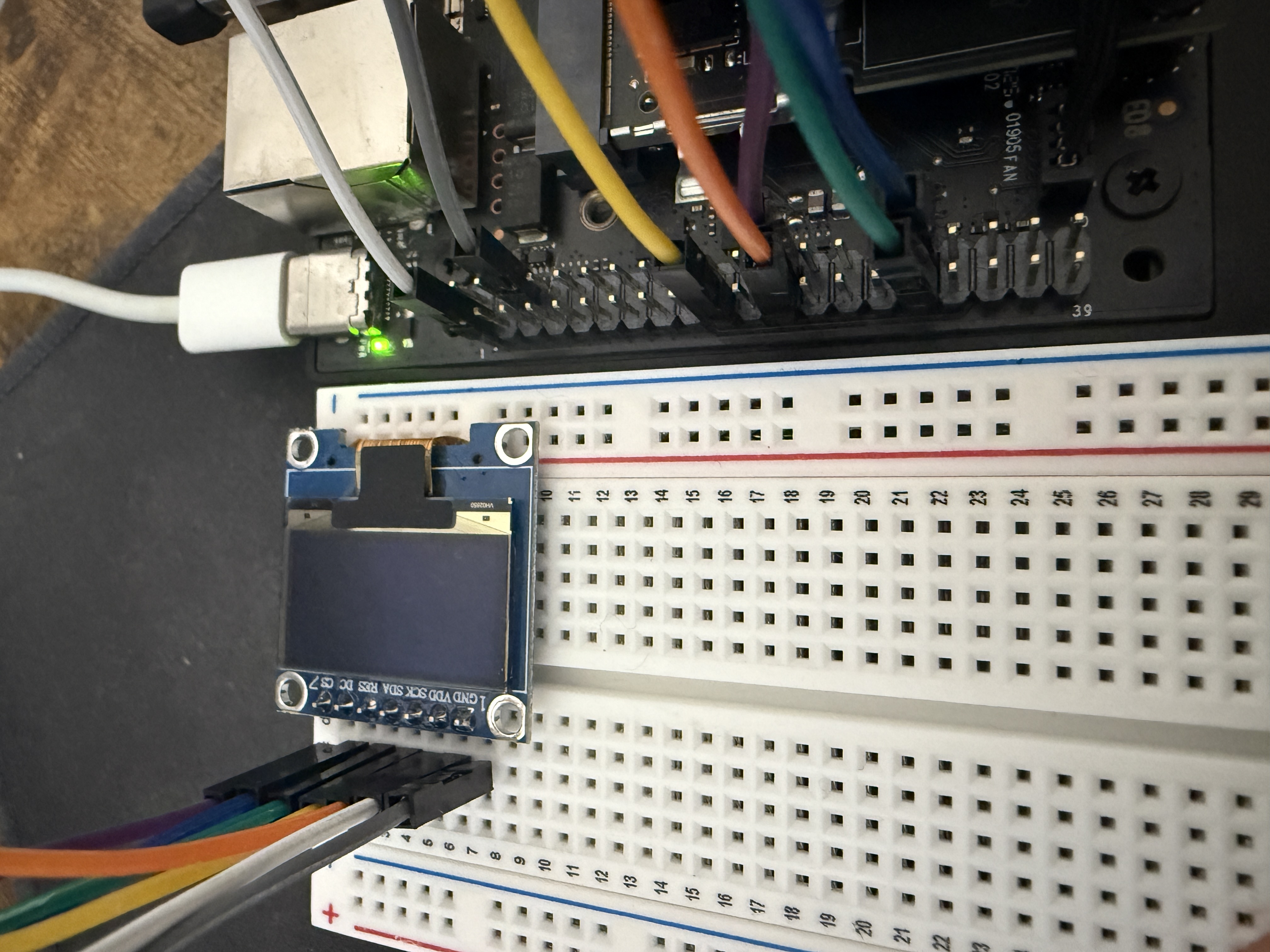
Wiring
2. Configure the Device-Tree Overlay
The SPI controller and GPIO pins must be activated via a device-tree overlay. jetson-io.py handles this without manually editing DTS files.
2.1 Check the current boot config
Before making any changes, note the current state of extlinux.conf so we can verify what changed afterwards.
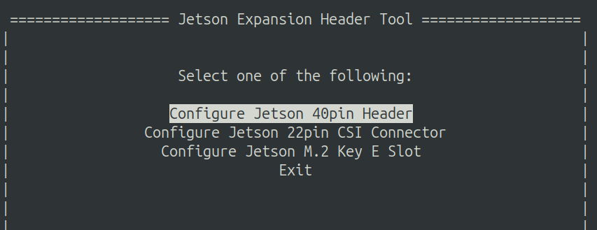
2.2 Run jetson-io.py
2.3 Select Configure Jetson 40pin Header
2.4 Select Configure header pins manually
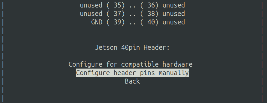
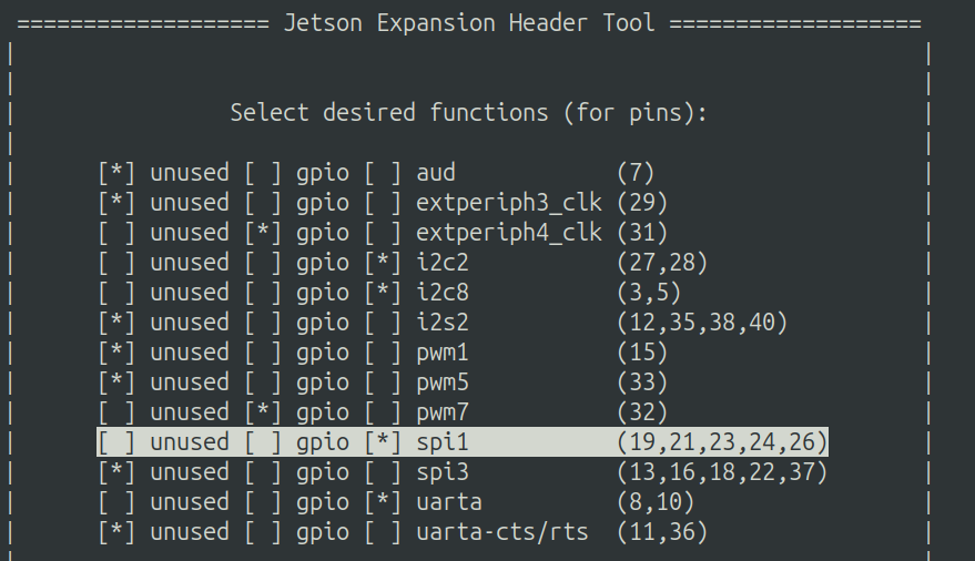
2.5 Set pin functions
Change the following assignments:
- Pin 19, 21, 23, 24, 26 →
spi - Pin 31 →
gpio - Pin 32 →
gpio
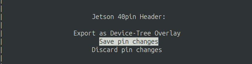
2.6 Save pin changes
Select Back, then Save pin changes.
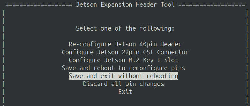
2.7 Exit without rebooting
Select Save and exit without rebooting.
Warning
Always verify the config before rebooting. A bad overlay can prevent the system from booting, potentially requiring a full reflash.
3. Verify the Overlay
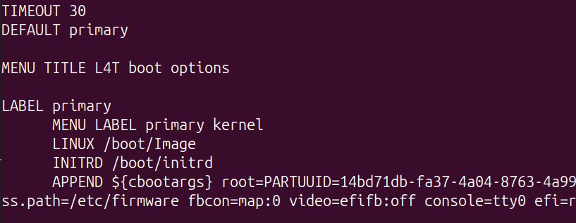
Check extlinux.conf
Open /boot/extlinux/extlinux.conf and confirm a new JetsonIO section has appeared, referencing jetson-io-hdr40-user-custom.dtbo.
Inspect the overlay (optional)
To read the raw DTS and confirm the SPI and GPIO pins are configured correctly, decompile the overlay:
# Copy the overlay to a working directory
$ mkdir -p ~/workspace
$ cp /boot/jetson-io-hdr40-user-custom.dtbo ~/workspace/

# Install the device-tree compiler
$ sudo apt-get install device-tree-compiler

# Decompile
$ dtc -I dtb -O dts ~/workspace/jetson-io-hdr40-user-custom.dtbo -o ~/workspace/temp.dts

# Inspect
$ cat ~/workspace/temp.dts
The DTS shows the SPI controller node and the two GPIO pins wired to RES and DC.
4. Reboot
5. Run the Python Test
$ git clone git@github.com:rylanpeng/jetson-orin-nano-ssd1306-spi.git
$ cd jetson-orin-nano-ssd1306-spi
$ uv sync
$ uv run python display.py
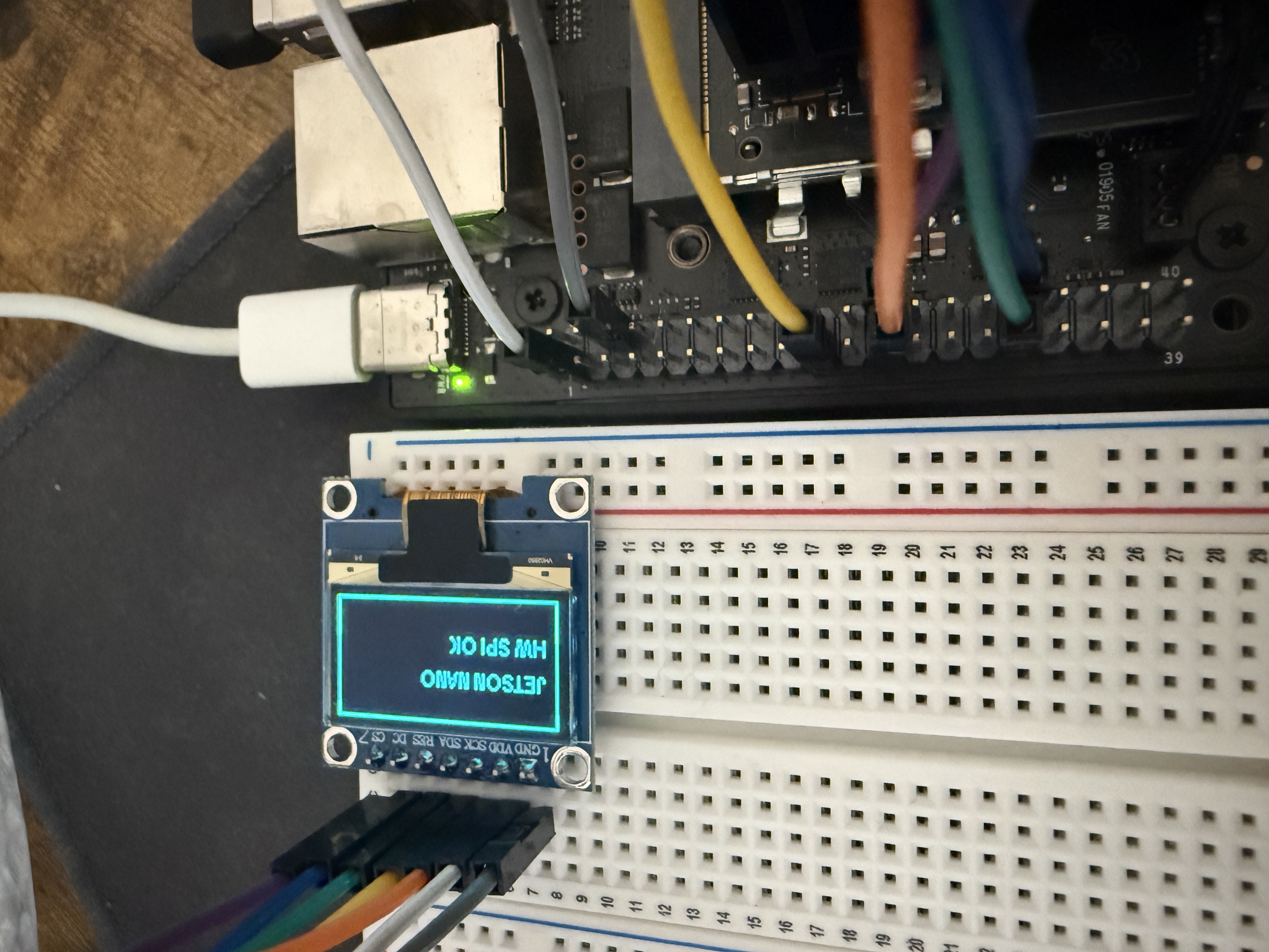
Result